Water-regenerable activated carbon filters are a unique and increasingly specified subclass of gas-phase odour control systems in which the carbon media can be regenerated on-site by washing with water, eliminating the need to remove, transport, and thermally reactivate the carbon. This is inherently different from standard activated carbon systems, which require replacement or off-site thermal reactivation once fully saturated.
The term ‘water-regenerable activated carbon’ appears with increasing frequency in specification documents for infrastructure projects — especially sewage pumping stations (SPS), sewage lift stations, stormwater pumping stations, and small- to medium-sized sewage treatment plants (STP).
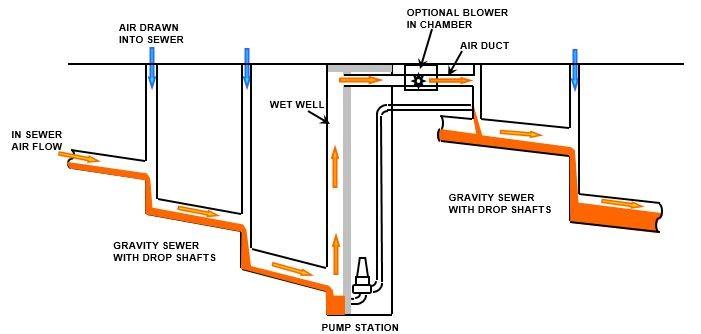
The growth in water-regenerable carbon specifications in pump station and STP tenders is driven by a clearly identifiable set of operational and economic pressures that are particularly acute in the sewage infrastructure context:
2.1 The Chemistry of Regeneration for KOH-Impregnated Carbon
The primary reactions when KOH-impregnated activated carbon captures H₂S are:
Capture reaction: H₂S + 2KOH → K₂S + 2H₂O (This makes potassium sulphide form on the surface of the carbon. )
With oxygen present: 2K₂S + 2O₂ + 2H₂O → 4KOH + 2S (This means KOH is partly regenerated. Elemental sulphur is left behind. )
Over time, bed capacity is depleted through three progressive mechanisms:
(1) KOH impregnant consumption: The alkaline impregnant is converted to potassium sulphide, potassium sulphate, and potassium thiosulphate through repeated reaction with H₂S. As the available KOH is consumed, the chemisorption capacity of the bed declines proportionally.
(2) Elemental sulphur accumulation: The partial self-regeneration reaction produces elemental sulphur as a by-product, which deposits progressively within the micropore structure. Being hydrophobic and insoluble, elemental sulphur is not fully removed by water washing and accumulates with each service cycle, gradually reducing accessible pore volume.
(3) Reaction by-product adsorption: Potassium thiosulphate, potassium sulphate, and other ionic reaction products occupy adsorption sites on the carbon surface. While the water-soluble fraction is removed during each wash cycle, a residual accumulation occurs over successive cycles, contributing to the gradual decline in regenerable capacity observed over the carbon bed’s service life.
Washing the carbon with water helps get it working again in two ways:
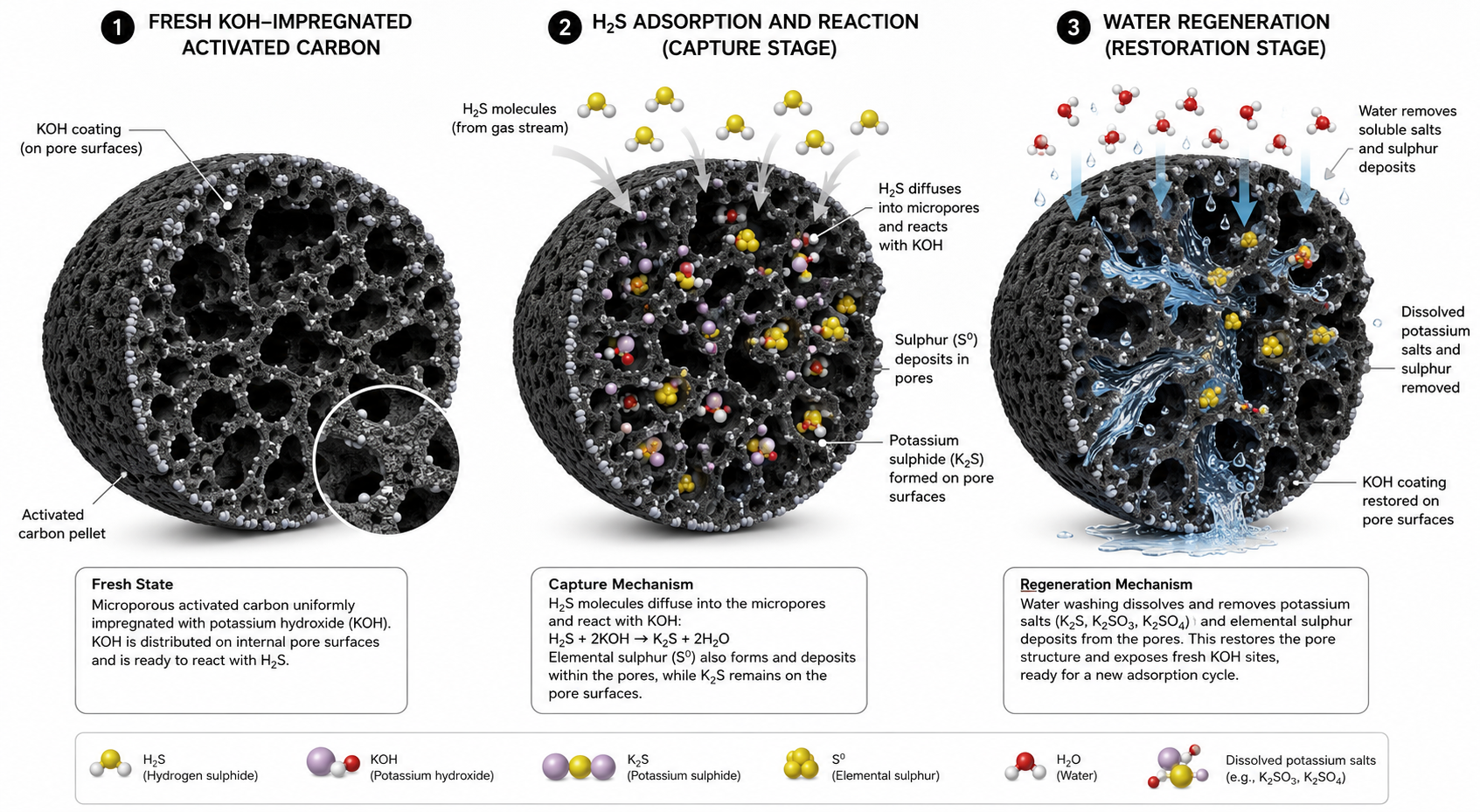
2.2 Re-impregnation During Water Regeneration
The most advanced water-regenerable systems simultaneously wash and re-impregnate by pumping a dilute KOH (or NaOH) solution through the bed. This wash-and-reimpregnate cycle:
After the wash cycle, the carbon bed must be dried — by passing ambient or heated air through it — before returning to active odour control service. The drying step is critical: returning a wet carbon bed to air-phase service without adequate drying severely compromises adsorption performance. In humid climates such as India, where ambient RH regularly exceeds 80–90%, the drying period must be explicitly engineered into the system design.
2.3 Carbon Types Suitable for Water Regeneration
2.4 Water Washing for Short-Chain Acid Vapour Streams
A specialised and practically useful technique is periodic water washing of gas-phase carbon beds treating acetic acid, formic acid, or similar water-soluble, short-chain fatty acid vapours. These occur in rubber processing, food manufacturing, and fermentation facilities.
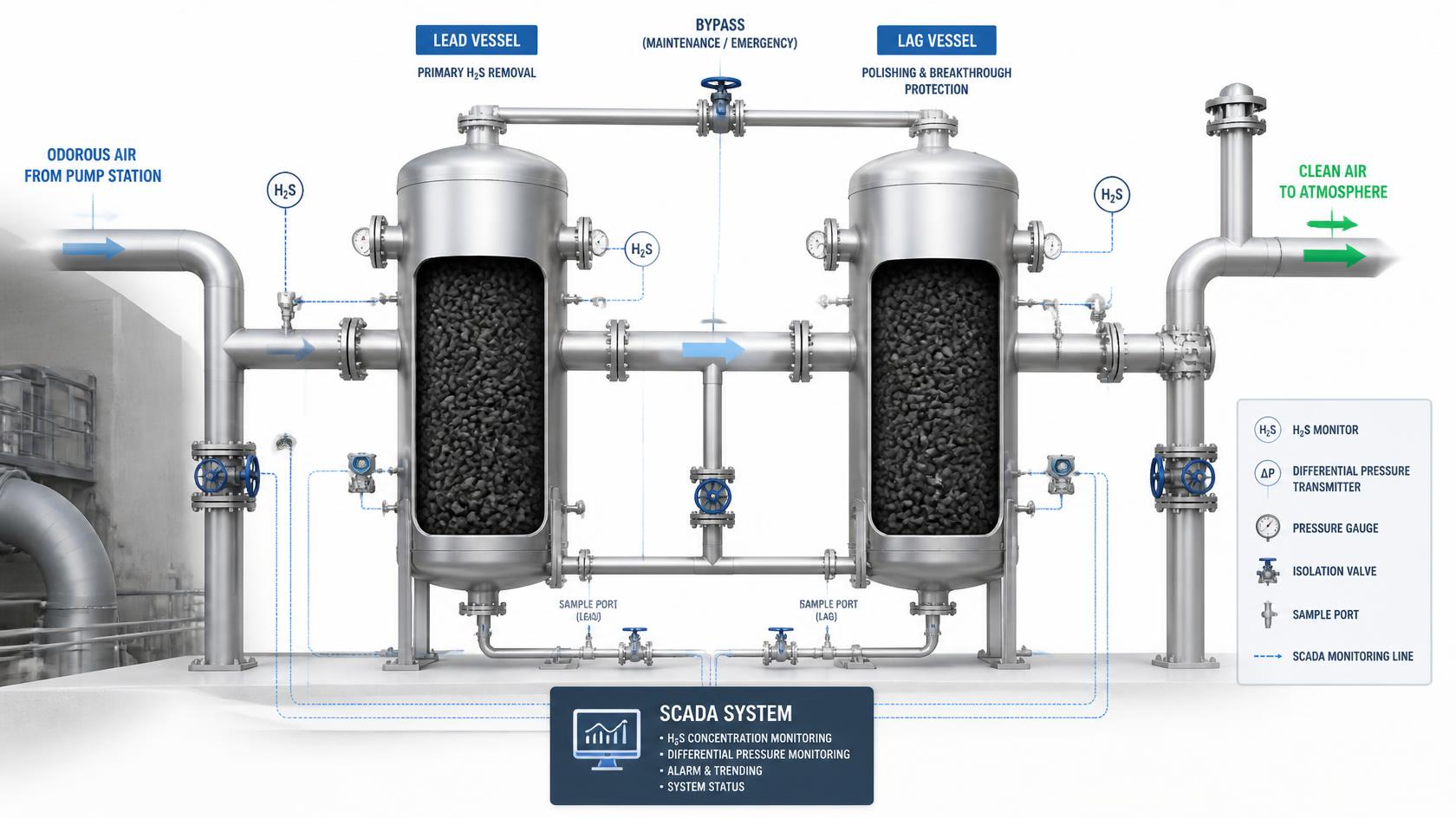
3.1 Single-Stage vs. Lead-Lag (Series) Configuration
A single carbon vessel operates until the bed is exhausted, at which point breakthrough can occur without warning or regeneration of the entire vessel — an operational vulnerability if breakthrough occurs unexpectedly. A Lead-Lag (or series) arrangement is the preferred industrial configuration:
3.2 Bed Depth and Pressure Drop
Minimum bed depth is dictated by the required EBCT and the need for an adequate mass transfer zone. A typical minimum bed depth for gas-phase applications is 0.3–0.5 m; beds of 0.5–1.0 m are more common for industrial odour control. Deeper beds extend service life but increase pressure drop. Coarser granules reduce pressure drop but also reduce adsorption efficiency per unit bed volume.
3.3 Pre-treatment Requirements
The quality of the inlet stream significantly influences the performance and life of activated carbon systems. The following pre-treatment stages are typically required:
3.4 Monitoring and Breakthrough Detection
4.1 Thermal Reactivation
Spent GAC can be thermally reactivated in rotary kilns or multiple hearth furnaces at 700–950°C with steam injection to desorb and combust adsorbed compounds. Reactivated carbon typically recovers 90–95% of its original surface area. In-house reactivation is only economical for operations consuming more than approximately 1,000 tonnes/year of carbon.
4.2 Steam Regeneration
Low-pressure steam desorbs adsorbed VOCs from carbon beds on site. The VOC-rich effluent is condensed downstream and separated into an aqueous phase and an organic phase — allowing solvent recovery where the recovered solvent has commercial value. This approach is used in solvent recovery systems (printing, rubber compounding). Steam regeneration is not appropriate for KOH or acid-impregnated carbons — the chemisorbed reaction products (K₂S, ammonium phosphate salts) are stable ionic compounds that cannot be thermally desorbed at steam temperatures — they require water washing or chemical treatment to remove.
4.3 Spent Carbon Disposal
Where carbon has reached the end of its serviceable life and cannot be further recycled, it must be disposed of in accordance with applicable hazardous waste regulations. In India, spent activated carbon used in industry is considered Schedule I hazardous waste. This means it has to be handled in accordance with specific rules, including strict tracking and disposal at an authorised site. When looking at different technologies, remember to include the cost of getting rid of the carbon in the overall expenses.
For very small odour control applications — sewage pump stations, small lift stations, minor STP vent streams, and enclosed chambers with ventilation air flows typically below 500–1,000 m³/h — activated carbon offers a decisive capital cost advantage over alternative treatment technologies such as biofilters and wet chemical scrubbers. This is not a question of performance — a correctly designed biofilter or scrubber will perform well at any scale. The issue is purely one of proportionate capital investment: at very small flows, these technologies carry a fixed infrastructure cost that does not scale down with flow rate.
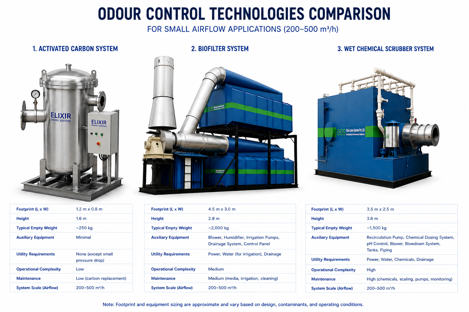
5.1 Why Biofilters Become Disproportionately Capital-Heavy at Very Small Flows
5.2 Why Scrubbers Become Disproportionately Capital-Heavy at Very Small Flows
Wet chemical scrubbers have fixed costs like chemical storage tanks, dosing pumps, pH monitors, and blowdown systems. These costs don’t go down much even when treating less air. For a pump station that maintenance staff only check in on occasionally, managing chemicals and waste becomes a lot more complicated than it’s worth for the small amount of air being cleaned.
5.3 Why Activated Carbon Is the Optimal Specification at Very Small Flows
Activated carbon delivers consistent adsorption performance across the full range of ventilation flows typical of sewage pump station and small STP applications. You can use a simple vessel filled with KOH-impregnated carbon to remove H₂S immediately, whether you’re treating 100 m³/h or 1,000 m³/h. The vessel design, installation, and operation are The vessel design, installation approach, and passive reagent-free operation remain essentially unchanged across this flow range, and it doesn’t need any chemicals.
The crossover point at which a biofilter or scrubber becomes more cost-effective on a whole-life basis typically occurs above 1,500–2,000 m³/h for H₂S-dominated sewage odour streams. Below this threshold, activated carbon — and especially water-regenerable activated carbon — is consistently the most economical and operationally appropriate specification.
Key Principle: Biofilters, scrubbers, and other active treatment technologies are excellent choices at large scale — and Elixir Enviro Systems designs and supplies all of these. At very small flows, the same technologies carry a capital cost that is disproportionate to the flow being treated. Activated carbon is the correct economic and operational choice for small sewage infrastructure — and the most appropriate specification in pump station and small STP tenders.
Q: What is water-regenerable activated carbon and why is it specified in pump station and lift station tenders?
Water-regenerable activated carbon refers to an activated carbon system — typically KOH-impregnated coconut shell pellets — designed to be regenerated on-site using a water wash (with or without KOH re-impregnation) rather than requiring carbon replacement or off-site thermal reactivation. The wash cycle dissolves the water-soluble potassium sulphide and sulphate compounds that form when the carbon captures H₂S, partially restoring adsorption capacity. More advanced systems re-impregnate the carbon with fresh KOH solution during the wash cycle, more fully restoring capacity. Water-regenerable systems are appearing increasingly in pump station tenders because these facilities are unmanned, require low-maintenance odour control, and benefit from automated in-situ regeneration that eliminates the need for periodic carbon replacement visits.
Q: How do you know when to replace water-regenerable activated carbon? And is it true that water-regenerable carbon lasts 2–5 times longer than conventional carbon?
A well-designed water-regenerable system with proper KOH re-impregnation during each wash cycle can restore 60–80% of the original H₂S capture capacity per cycle — meaning the total H₂S captured per kg of carbon can be 2–5 times higher than a conventional non-regenerable system. This is the correct basis for the extended life claim — it is a cumulative capture capacity advantage, not a simple time extension.
Knowing when to replace requires a combination of complementary approaches:
Best Practice Recommendation: For pump stations in residential or sensitive locations, install a fixed H₂S sensor at the carbon bed outlet connected to the station SCADA — this gives continuous, automated breakthrough detection. For smaller unmanned stations, combine a conservative fixed regeneration schedule with inlet H₂S monitoring at quarterly maintenance visits.
Q: How do I estimate how long activated carbon will last for a given pollutant concentration — and how does that change if the concentration changes?
This is a design-stage question, distinct from breakthrough monitoring (which tells an operator when carbon in an already-installed system needs replacing). Estimating expected service life before the system is built allows the bed size and the initial replacement or regeneration schedule to be specified correctly from the outset.
The starting point is a simple mass balance: Service life (hours) = (Carbon mass × Working capacity) ÷ (Flow rate × Inlet concentration). The inlet concentration must be converted from ppm to mass units — for gas-phase work, mg/m³ = ppm × (molecular weight ÷ 24.45) at 25°C. For H₂S (molecular weight 34), 1 ppm ≈ 1.39 mg/m³.
Worked example: a pump station carbon vessel holds 500 kg of KOH-impregnated coconut shell carbon, with a working H₂S capacity of 0.08 g per gram of carbon. At a flow rate of 1,000 m³/h and an inlet H₂S concentration of 20 ppm (≈27.8 mg/m³, or 0.0278 g/m³), the mass of H₂S entering the bed is 1,000 × 0.0278 = 27.8 g per hour. The total bed capacity is 500,000 × 0.08 = 40,000 g H₂S. Dividing the two gives a service life of approximately 1,440 hours — roughly two months.
An important nuance: doubling the inlet concentration does not always halve the service life — the relationship depends on the adsorption mechanism.
The 0.08 g/g figure used in the worked example is a working capacity, not the equilibrium or saturation capacity quoted in vendor isotherm data — which for KOH-impregnated carbon is often in the 0.15–0.20 g/g range. Working capacity is typically 30–50% of the equilibrium value, accounting for the portion of the bed occupied by the Mass Transfer Zone at breakthrough, channelling, competitive adsorption from humidity, and the safety margin built into the design.
This calculation provides a sound basis for sizing the bed and setting an initial replacement or regeneration schedule at the design stage. Once the system is operating, the breakthrough monitoring approach described above — particularly a fixed H₂S sensor at the bed outlet — remains the more reliable method, since it accounts for the real seasonal and operational variability that no design formula can fully capture.
Q: For small odour control applications like pump stations and small STPs, why is activated carbon often the best technology choice over biofilters or scrubbers?
This is a question of proportionate capital cost, not of technology performance. A biofilter or scrubber will work perfectly well at any scale — but at very small flows, these technologies carry a baseline infrastructure cost that does not scale down proportionally. A biofilter for 200–500 m³/h must still achieve 15–60 seconds of EBRT, still requires a humidification system, and still requires a structurally significant tank — regardless of the small flow rate. A scrubber still requires chemical storage, a dosing pump, pH monitoring, and blowdown management. Activated carbon, by contrast, scales with almost no penalty — the cost difference between a carbon system for 200 m³/h and one for 800 m³/h is primarily the mass of media, not civil infrastructure or chemical systems. The crossover point at which biofilter or scrubber lifecycle economics become more favourable typically occurs above 1,500–2,000 m³/h for sewage odour streams.
Q: Is Activated Carbon Fibre (ACF) cost-effective compared to conventional GAC for small odour control units?
ACF and conventional GAC represent two fundamentally different forms of the same material, with different cost profiles. ACF media costs significantly more per kilogram than coconut shell GAC — typically 5–10 times more. However, because ACF has extremely fast adsorption kinetics (due to its microporous fibre structure with very short diffusion paths), far less media mass is needed to achieve the same removal. For very small odour control units (below 300–500 m³/h), this can produce a lower total capital cost for the ACF-based unit compared to a GAC vessel system. However, ACF cartridges have less total media mass, so they reach saturation faster on heavier-loaded streams and require more frequent replacement or regeneration. ACF is most relevant for very small, lightly loaded streams where physical compactness is the primary design constraint. For pump stations with meaningful H₂S loads, conventional coconut shell GAC in a properly sized vessel provides the better balance of capital cost, media capacity, and operational lifecycle.